- Samgomould
- 21 Dic 2025
The Structure and Systems of Injection Molds: A Comprehensive Guide
Introduction
Injection molding is one of the most widely used manufacturing processes for producing plastic parts, from simple household items to complex automotive components. At the heart of this process lies the injection mold—a precision tool that dictates the quality, consistency, and efficiency of production. This article explores the intricate structure and sophisticated systems of injection molds, providing a detailed overview of their design, functionality, and operation.
1. Fundamental Structure of Injection Molds
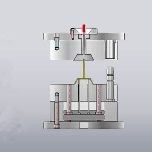
An injection mold is typically composed of two main halves: the stationary half (cavity side) and the moving half (core side). These halves come together under pressure to form the cavity into which molten plastic is injected.
1.1 Mold Base Components
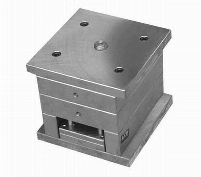
The mold base serves as the structural foundation, housing all other components:
| Component | Función | Material |
|---|---|---|
| Clamping Plate | Connects the mold to the injection molding machine | P20, 4140 Steel |
| Cavity Plate | Contains the impression(s) that form the part’s exterior | H13, S7 Tool Steel |
| Core Plate | Contains the core(s) that form the part’s interior features | H13, S7 Tool Steel |
| Support Plate | Prevents deflection of the core plate under injection pressure | 4140 Steel |
| Ejector Housing | Provides space for the ejection system components | 4140 Steel |
| Guide Pins/Bushings | Ensures precise alignment of mold halves | Carbide, Tool Steel |
1.2 Mold Cavity and Core
The cavity and core are the most critical components, forming the actual shape of the plastic part:
Cavity: Forms the external surfaces of the part
Core: Forms the internal features and often includes undercuts
Parting Line: The plane where the cavity and core meet
2. Essential Mold Systems
2.1 Injection System
The injection system guides molten plastic from the machine nozzle to the mold cavities:
Sprue: The primary channel from the machine nozzle
Runners: Channels that distribute plastic to multiple cavities
Gates: Controlled entry points into the cavity
Cold Slug Well: Catches the initial cooled plastic from the nozzle
| Gate Type | Description | Typical Applications | Advantages |
|---|---|---|---|
| Edge Gate | Located on part edge | Most common for simple parts | Easy to remove, versatile |
| Tab Gate | Small tab extension | Technical parts requiring precise filling | Reduces stress, clean removal |
| Pin Point Gate | Very small diameter point | Multi-cavity molds, small parts | Automatic separation, minimal marks |
| Hot Runner Gate | Heated system, no runner waste | High-volume production | No waste, faster cycles |
2.2 Cooling System
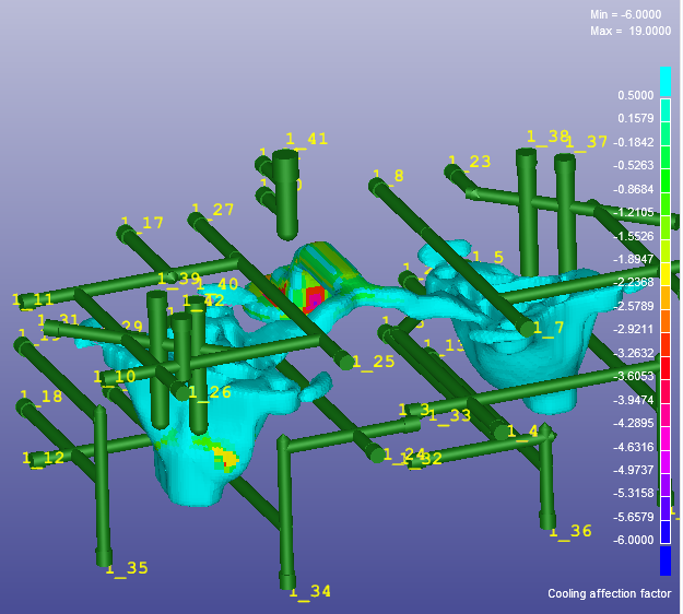
Effective cooling is crucial for cycle time and part quality:
Cooling Channels: Circulate water or oil to remove heat
Baffles and Bubbler Systems: Enhance cooling in deep cores
Thermal Pins: Transfer heat from difficult-to-cool areas
2.3 Ejection System
The ejection system removes solidified parts from the mold:
Pasadores expulsores: Most common method, push parts from core
Sleeve Ejectors: Used around cylindrical features
Stripper Plate: Lifts parts off the core (for thin-walled parts)
Eyector de aire: Uses compressed air to assist part removal
2.4 Venting System
Proper venting prevents defects by allowing air to escape:
Shallow Channels: Typically 0.01-0.03mm deep at parting line
Vent Pins: Ejector pins with ground flats for air passage
Porous Metal Inserts: Allow air escape while blocking plastic
3. Specialized Mold Systems
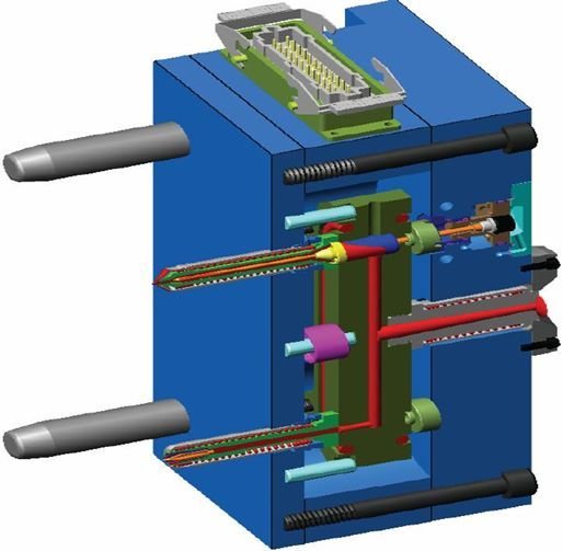
3.1 Side-Action Systems
For parts with undercuts that cannot be formed by simple mold opening:
Slides: Move perpendicular to mold opening direction
Angled Lifters: Convert vertical motion to horizontal movement
Hydraulic/Pneumatic Cylinders: Power complex movements
3.2 Hot Runner Systems
Advanced systems that keep plastic molten in the runners
| System Type | Description | Aplicaciones |
|---|---|---|
| Insulated Runner | Thick runners with insulating skin | Low to medium volume |
| Hot Manifold | Heated manifold with nozzles | Medium to high volume |
| Valve Gated | Positively controlled shut-off nozzles | Precision parts, multi-material |
3.3 Core Pull Systems
For creating internal undercuts or complex geometries:
Collapsible Cores: For threaded parts
Rotating Cores: Driven by gears or chains
Expandable Cores: For internal undercuts
4. Advanced Mold Technologies
4.1 Multi-Material Molding
Overmolding: Sequential injection of different materials
Co-injection: Simultaneous injection through separate gates
Stack Molds: Multiple parting lines for increased output
4.2 Intelligent Mold Systems
Modern molds incorporate sensors and monitoring:
Pressure Sensors: Monitor cavity pressure for quality control
Temperature Sensors: Ensure consistent thermal management
Ejection Sensors: Verify complete part removal
4.3 Quick-Change Systems
For rapid mold changeover in production:
Standardized Mounting: Quick clamping systems
Modular Components: Interchangeable inserts
Pre-wired Connections: Integrated heating and sensing
5. Mold Design Considerations
5.1 Material Selection
Factors influencing mold material choice:
Production Volume: Higher volumes require harder, more durable steels
Part Material: Abrasive or corrosive plastics require special steels
Part Complexity: Detailed features may require superior polishability
5.2 Maintenance and Durability
Key design aspects for mold longevity:
Wear Resistance: Critical areas should use hardened steels or coatings
Accessibility: Easy access for cleaning and maintenance
Standardization: Use standard components when possible
6. Mold Manufacturing Process
| Process Step | Description | Equipment Used |
|---|---|---|
| Design & Engineering | 3D modeling, simulation, DFM analysis | CAD/CAM software, Moldflow |
| Material Preparation | Cutting, squaring steel blocks | CNC mills, saws |
| Rough Machining | Removing bulk material | Large CNC mills |
| Heat Treatment | Hardening critical components | Vacuum furnaces |
| Precision Machining | Creating detailed features | CNC, EDM machines |
| Finishing | Polishing, texturing | Polishing tools, EDM texturing |
| Assembly | Fitting all components together | Assembly benches |
| Testing & Sampling | Verifying mold performance | Injection molding machine |
Conclusión
The injection mold is a masterpiece of precision engineering, combining multiple systems that must work in perfect harmony to produce quality plastic parts efficiently. From the basic cavity and core to sophisticated hot runner systems and intelligent monitoring, each component plays a critical role in the molding process.
As materials become more advanced and part designs more complex, mold technology continues to evolve. Modern injection molds represent significant investments but deliver unparalleled manufacturing capability when designed and built correctly.
Ready for Your Next Project?
Are you planning a new injection molding project? Our team of experienced engineers and mold makers specializes in designing and building precision molds that deliver exceptional performance and longevity. We offer:
Expert Design Consultation: DFM analysis to optimize part design for manufacturability
Advanced Mold Manufacturing: State-of-the-art equipment and proven processes
Comprehensive Support: From prototyping to full-scale production
Quality Assurance: Rigorous testing and sampling before delivery
Request a quotation today! Contact our team with your part drawings, specifications, and production requirements. We’ll provide a detailed proposal including design recommendations, timeline, and competitive pricing.
Hi,ok