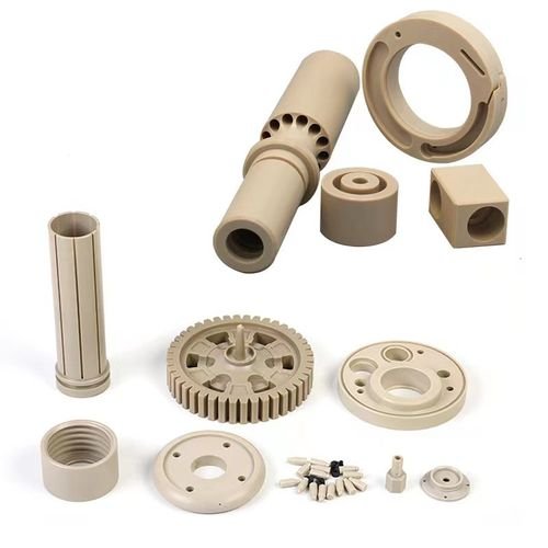
PEEK injection molding
- Home
- / Material /
- PEEK injection molding
PEEK Injection Moulding: Mastering High-Performance Polymer Processing
1. Introduction: The Pinnacle of Engineering Plastics
Polyether ether ketone (PEEK) represents the apex of high-performance thermoplastics, combining exceptional mechanical properties, thermal stability, and chemical resistance in ways that no other polymer can match. First commercialized in the 1980s, this semi-crystalline super-engineering polymer has become indispensable in applications where failure is not an option – from deep-sea oil exploration to aerospace propulsion systems and life-sustaining medical implants. With its ability to withstand continuous service temperatures up to 260°C (500°F) while maintaining structural integrity, PEEK injection moulding stands as one of the most demanding and technically sophisticated manufacturing processes in the polymer industry.
This comprehensive guide explores the intricate world of PEEK injection moulding, examining the material’s unique characteristics, specialized processing requirements, and the exacting standards necessary to produce components that routinely operate in extreme environments. We will uncover why PEEK commands premium pricing yet delivers unparalleled value in critical applications, and how advances in processing technology continue to expand its boundaries in demanding sectors.
2. Material Science: Understanding PEEK’s Exceptional Properties
Chemical Architecture:
PEEK belongs to the PAEK (polyaryletherketone) family, characterized by an alternating structure of aromatic rings connected by ketone and ether functional groups. This molecular architecture provides:
Key Structural Features:
Aromatic Backbone: Provides thermal stability and rigidity
Ketone Groups: Contribute to high temperature resistance
Ether Linkages: Offer some chain flexibility
Crystalline Structure: 30-35% crystallinity typical in molded parts
Material Grades and Modifications:
| Grade Type | Key Characteristics | Typical Applications |
|---|---|---|
| Virgin PEEK | Unfilled, natural color | Medical implants, semiconductor |
| 30% Glass-Filled | Enhanced stiffness, dimensional stability | Structural components, bearings |
| 30% Carbon-Filled | Superior strength, conductivity | Aerospace, automotive racing |
| PTFE-Filled | Reduced friction, wear resistance | Bushings, seals, bearings |
| Carbon Fiber Reinforced | Highest strength-to-weight ratio | Aerospace structures |
| Medical Grade | ISO 10993, USP Class VI compliant | Spinal implants, dental components |
Exceptional Property Matrix:
| Property | Value Range | Comparison Advantage |
|---|---|---|
| Continuous Service Temp | 260°C (500°F) | Highest among thermoplastics |
| Tensile Strength | 90-100 MPa (unfilled) | Comparable to aluminum |
| Flexural Modulus | 3.6-4.0 GPa (unfilled) | Stiff engineering performance |
| HDT @ 1.82 MPa | 160°C (320°F) | Unmatched for thermoplastics |
| Chemical Resistance | Excellent | Withstands most chemicals |
| Wear Resistance | Excellent | Superior to many metals |
| Flame Rating | UL94 V-0 | Self-extinguishing |
| Radiation Resistance | Excellent | Medical sterilization compatible |
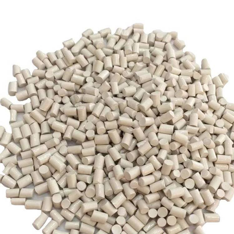
3. Material Preparation: The Critical Pre-Processing Phase
Extreme Drying Imperatives:
PEEK is highly hygroscopic with moisture absorption up to 0.5% at equilibrium. Improper drying causes catastrophic defects:
Drying Specifications:
Target Moisture: <0.02% (200 ppm) for critical applications
Drying Temperature: 150°C (302°F) minimum, 180°C (356°F) optimal
Drying Time: 4-6 hours minimum, 8+ hours recommended
Dew Point: -40°C (-40°F) or lower mandatory
Hopper Design: Closed-loop drying with sufficient residence time
Consequences of Insufficient Drying:
Hydrolytic Degradation: Water causes chain scission at high temperatures
Surface Defects: Severe splay, silver streaks, bubbles
Property Loss: Dramatic reduction in mechanical properties
Molecular Weight Drop: Irreversible damage to polymer chains
Processing Issues: Inconsistent flow, poor dimensional control
Material Handling Protocol:
Storage Environment: 23°C ±2°C, <30% relative humidity
Controlled Access: Limit exposure to ambient air
Container Management: Sealed with desiccant when not in use
Time Limits: Maximum 1-2 hours exposure during material changes
Regrind Management Strategy:
Maximum Regrind: 10-15% for critical applications
Thermal History Tracking: Each cycle degrades properties
Separate Processing: Dedicated equipment recommended
Testing Protocol: Regular melt flow and mechanical testing
Colorant Integration:
Limited Options: High processing temperatures restrict choices
Special Masterbatches: PEEK-compatible carriers required
Pre-compounded: Recommended for consistent results
Natural Preference: Many applications use natural color
4. Injection Moulding Machine Requirements
Premium Machine Specifications:
Temperature Capability:
Maximum Required: 400°C (752°F) minimum capability
Temperature Control: ±1°C precision throughout system
Heating Zones: Minimum 5-6 zones with PID control
Heater Bands: High-quality with uniform distribution
Insulation: Comprehensive to minimize heat loss
Screw Design Excellence:
Material: High-grade corrosion-resistant steel
L/D Ratio: 20:1 to 24:1 for proper melting
Compression Ratio: 2.5:1 to 3.0:1
Check Valve: High-performance sliding ring type
Screw Tip: Mixing elements for filled grades
Surface Treatment: Hard chrome or nitrided for wear resistance
Barrel and Nozzle System:
Barrel Material: Bimetallic with corrosion-resistant lining
Capacity: 40-70% of machine rating optimal
Nozzle Type: Open with precise temperature control
Thermocouples: Multiple for accurate temperature mapping
Wear Monitoring: Regular inspection and measurement
Clamping System:
Clamp Force: 4-8 tons per square inch (higher for filled grades)
Platen Parallelism: Critical for precision parts
Tie Bar Strength: Adequate for high injection pressures
Ejection System: Precise, controlled ejection essential
Control System Requirements:
Closed-Loop Control: For all critical parameters
Data Logging: Complete process documentation
Recipe Management: Multiple optimized parameter sets
Integration: With all auxiliary equipment
Auxiliary Equipment:
High-Temperature Dryers: Capable of 180°C operation
Precision Chillers: For mold temperature control
Robotic Systems: For part handling and quality assurance
Environmental Control: For consistent processing conditions
5. Processing Parameters and Optimization
Critical Temperature Parameters:
| Process Zone | Temperature Range | Critical Notes |
|---|---|---|
| Rear Barrel | 340-360°C (644-680°F) | Gentle preheating |
| Middle Zones | 360-380°C (680-716°F) | Main melting phase |
| Front Zone | 380-400°C (716-752°F) | Final homogenization |
| Nozzle | 380-400°C (716-752°F) | Match melt temperature |
| Melt Temperature | 380-400°C (716-752°F) | Critical for crystallization |
| Mold Temperature | 160-200°C (320-392°F) | Essential for properties |
Temperature Management Principles:
Minimum Temperature: Below 360°C risks incomplete melting
Maximum Temperature: Above 420°C causes degradation
Thermal Uniformity: ±5°C maximum variation in melt
Residence Time: Minimize to prevent thermal degradation
Injection Phase Optimization:
Injection Speed:
Fast to very fast injection recommended
Prevents premature freezing in mold
Maintains melt temperature through shear heating
Injection Pressure: 1000-2000 bar (higher for filled grades)
Switchover: 95-98% cavity fill by volume
Back Pressure: 10-20 bar for melt homogenization
Holding/Packing Phase Strategy:
Pressure: 60-80% of injection pressure
Time: Extended (15-30 seconds typical)
Function: Compensates for high shrinkage (1.2-2.0%)
Multi-Stage: Often beneficial for complex parts
Cooling and Crystallization Control:
Cooling Time: 60-120 seconds per mm thickness
Mold Temperature Critical: Controls crystallization rate and degree
Ejection Temperature: Below 200°C to prevent distortion
Annealing: Often required for optimal properties
Special Processing Techniques:
High-Speed Injection: For thin-walled parts
Gas-Assist Moulding: For thick sections
Sequential Gating: For large or complex parts
In-Mould Crystallization: Controlled cooling profiles
6. Tooling Design for PEEK Moulding
Premium Mold Materials:
Cavity/Core: Tool steels H13, S7, or stainless steels
Hardness Requirements: 48-52 HRC minimum
Corrosion Resistance: Essential for consistent performance
Surface Treatments: Nitriding, chrome plating, or PVD coatings
Thermal Conductivity: High conductivity materials preferred
Runner System Design:
Full Round Runners: 8-12mm diameter minimum
Runner Balancing: Critical for multi-cavity molds
Hot Runner Systems: Externally heated with precise control
Gate Types:
Edge Gates: Most common
Direct Sprue: For single-cavity molds
Diaphragm Gates: For cylindrical parts
Hot Tips: For cosmetic surfaces
Temperature Control System:
High-Temperature Capability: Up to 200°C operation
Conformal Cooling: Follows part contours closely
Multiple Circuits: Separate control for different zones
Temperature Uniformity: ±3°C across mold surface
Heated Manifolds: For consistent temperature distribution
Venting System Design:
Vent Depth: 0.010-0.020mm (shallower than many materials)
Vent Width: 6-10mm
Strategic Placement: All end-of-fill areas
Vacuum Venting: Recommended for critical parts
Regular Maintenance: Essential for consistent performance
Ejection System Considerations:
Ejector Pins: Larger diameter to reduce surface pressure
Material Selection: High-temperature resistant steels
Surface Finish: Highly polished to prevent sticking
Ejection Force: Higher due to high stiffness
Sequenced Ejection: For complex geometries
Surface Finish Requirements:
Optical Quality: SPI A-1 for medical and optical parts
Texture Options: Available but affects crystallization
Polish Direction: Consistent to avoid visual defects
Maintenance: Regular polishing to maintain quality
7. Crystallinity Control and Annealing Processes
Understanding PEEK Crystallinity:
Crystalline Content: Typically 30-35% in as-molded parts
Crystallization Temperature: 170-190°C (338-374°F)
Crystal Structure: Orthorhombic unit cells
Property Dependence: Mechanical properties directly related to crystallinity
Factors Affecting Crystallinity:
| Factor | Effect on Crystallinity | Process Control |
|---|---|---|
| Mold Temperature | Higher temp = higher crystallinity | Precise temperature control |
| Cooling Rate | Slower cooling = higher crystallinity | Controlled cooling profiles |
| Nucleating Agents | Increase crystallization rate | Material formulation |
| Molecular Weight | Lower MW = higher crystallinity | Material grade selection |
| Part Thickness | Thicker = higher crystallinity | Design consideration |
Annealing Processes:
Purpose: Increase crystallinity, relieve stresses, improve properties
Temperature: 200-220°C (392-428°F) for 2-4 hours
Atmosphere: Inert gas or vacuum to prevent oxidation
Cooling Rate: Controlled (1-2°C per minute) to room temperature
Benefits: Increased HDT, improved chemical resistance, dimensional stability
Crystallinity Measurement Methods:
DSC (Differential Scanning Calorimetry): Most common method
XRD (X-ray Diffraction): For crystal structure analysis
Density Measurement: Indirect method using density-crystallinity relationship
FTIR Spectroscopy: For chemical structure analysis
Processing for Optimal Crystallinity:
Mold Temperature: Maintain above 160°C for adequate crystallization
Holding Pressure: Sufficient to pack crystals during solidification
Cooling Rate: Controlled to allow proper crystal growth
Post-Mould Annealing: For maximum properties
8. Part Design Guidelines for PEEK
Wall Thickness Principles:
General Range: 1.0-6.0mm
Optimal Thickness: 2.0-3.0mm
Uniformity: Critical (maximum 20% variation)
Minimum Thickness: 0.5mm possible with optimized processing
Thick Sections: Core out to minimize sink marks and reduce stress
Radii and Corner Design:
Internal Radii: Minimum 0.5 times wall thickness
External Radii: Internal radius plus wall thickness
Stress Concentration: Avoid sharp corners completely
Transition Design: Gradual changes (3:1 maximum ratio)
Rib and Boss Design:
Rib Thickness: 40-50% of adjacent wall
Rib Height: Maximum 2.5 times wall thickness
Boss Design: Must be cored and connected with ribs
Draft Angles: 1-2° per side minimum
Fillet Radii: Generous at base connections
Draft Angle Requirements:
Standard Applications: 1-3° per side
High-Aspect Features: Additional draft may be required
Textured Surfaces: Add 1° per 0.025mm texture depth
Medical Implants: Minimum draft for precise fits
Tolerance Considerations:
Standard Tolerances: ±0.1% or ±0.1mm, whichever is greater
Critical Dimensions: ±0.05% achievable with optimization
Thermal Expansion: Account for 4.7 x 10^-5 /°C
Post-Mould Changes: Minimal due to high stiffness
Assembly Feature Design:
Snap-fits: Limited use due to high stiffness
Threads: Molded-in possible with proper design
Press-fits: Careful interference calculations required
Bonding: Designed for specialized adhesives
Mechanical Fastening: Preferred method for most applications
9. Quality Control and Testing Protocols
Material Qualification Testing:
Thermal Analysis:
DSC Analysis: Melting point (343°C), crystallinity percentage
TGA: Thermal stability, decomposition temperature
DMA: Dynamic mechanical properties
HDT/Vicat: Heat deflection and softening points
Mechanical Testing:
Tensile Properties: ASTM D638 at elevated temperatures
Flexural Testing: ASTM D790 for stiffness verification
Impact Resistance: ASTM D256 (Izod/Charpy)
Compressive Strength: ASTM D695 for structural applications
Chemical and Environmental:
Chemical Resistance: Immersion testing per ASTM D543
Hydrolytic Stability: Autoclave testing for medical parts
Radiation Resistance: Gamma sterilization compatibility
Aging Studies: Long-term property retention
Process Control Parameters:
Melt Temperature: Continuous infrared monitoring
Pressure Profiles: Injection and holding phase documentation
Cushion Consistency: ±0.2mm variation maximum
Cycle Time: Statistical process control implementation
Part Validation Testing:
Dimensional Verification: CMM with temperature compensation
Surface Quality: White light interferometry for critical parts
Non-destructive Testing: Ultrasonic or X-ray for internal defects
Functional Testing: Under application conditions
Certification and Documentation:
Material Traceability: Lot tracking from resin to finished part
Process Documentation: Complete parameter records
Quality Certifications: ISO 13485, AS9100, etc.
Customer-Specific Requirements: Often exceed industry standards
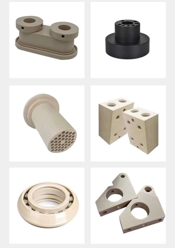
10. Industry Applications and Case Studies
Aerospace and Defense:
Aircraft Components: Brackets, clips, fasteners (25% weight savings vs metal)
Engine Components: Seals, bushings, wear pads
Interior Components: Meeting FAA flammability requirements
Space Applications: Radiation-resistant components
Medical Technology:
Orthopedic Implants: Spinal cages, joint replacements
Dental Instruments: Autoclavable handles and components
Surgical Tools: Lightweight, MRI-compatible instruments
Drug Delivery: Components for infusion pumps
Oil and Gas Industry:
Downhole Components: Seals, bushings, wear rings
Subsea Equipment: Electrical connectors, sensor housings
Valve Components: Seats, seals, guiding elements
Chemical Processing: Pump components, valve parts
Semiconductor Manufacturing:
Wafer Handling: Carriers, end effectors
Process Chamber: Components for plasma environments
Chemical Delivery: Valves, fittings, tubing
Clean Room Equipment: Low particle generation components
Automotive Racing:
Engine Components: Seals, bushings, bearings
Transmission Parts: Wear components, seals
Suspension Components: Bushings, bearings
Electrical Systems: Connectors, sensor housings
Industrial Applications:
Bearings and Bushings: For high-temperature environments
Seals and Gaskets: Chemical and temperature resistance
Electrical Insulation: For high-temperature applications
Wear Components: Superior to many metals
11. Troubleshooting Common PEEK Defects
| Defect | Root Causes | Corrective Actions | Prevention Strategies |
|---|---|---|---|
| Surface Delamination | Moisture contamination, overheating | Verify drying, reduce temperatures | Strict moisture control, temp monitoring |
| Bubbles/Voids | Moisture, insufficient packing | Improve drying, increase pack pressure/time | Proper material handling, process optimization |
| Poor Crystallinity | Low mold temperature, fast cooling | Increase mold temp, adjust cooling rate | Proper mold temperature control |
| Warpage/Distortion | Non-uniform cooling, residual stress | Improve cooling uniformity, annealing | Balanced cooling design, post-mould treatment |
| Short Shots | Low temperature, inadequate pressure | Increase temps 10-20°C, increase pressure | Proper temperature settings, gate optimization |
| Sink Marks | Insufficient packing, thick sections | Increase holding pressure/time, modify design | Uniform wall design, adequate packing |
| Discoloration | Thermal degradation, excessive residence | Lower temperatures, reduce cycle time | Temperature control, optimized cycles |
| Poor Dimensional Stability | Inconsistent processing, improper annealing | Standardize process, implement annealing | Process control, post-mould treatments |
Material-Specific Challenges:
Thermal Degradation: Above 420°C causes permanent damage
Crystallinity Control: Critical for consistent properties
Moisture Sensitivity: Extreme sensitivity requires rigorous control
High Shrinkage: Requires precise mold design compensation
Preventive Quality Measures:
Regular Equipment Calibration: Temperature sensors, pressure transducers
Material Testing: Incoming material qualification
Process Validation: DOE studies for parameter optimization
Continuous Monitoring: Real-time parameter tracking
12. Sustainability and Recycling Considerations
Recycling Challenges and Opportunities:
Mechanical Recycling:
Property Retention: Good with limited thermal history
Maximum Regrind: 10-15% for critical applications
Sorting Requirements: Must be separated from other polymers
Applications: Lower-grade applications possible
Chemical Recycling:
Depolymerization: Back to monomer possible but complex
Solvent Recovery: For certain applications
Pyrolysis: To chemical feedstocks
Current Status: Developing but not commercial scale
Energy Recovery:
Calorific Value: 32-34 MJ/kg (higher than many polymers)
Waste-to-Energy: Efficient option for contaminated material
Environmental Considerations: Halogen-free combustion
Sustainable Manufacturing Initiatives:
Energy Efficiency: Optimized processing reduces energy consumption
Material Optimization: Minimal waste through design
Extended Product Life: Long service life reduces environmental impact
Lightweighting: Replacing metals reduces energy in use phase
Industry Programs and Certifications:
Environmental Management: ISO 14001 implementation
Material Stewardship: Responsible sourcing and use
Life Cycle Assessment: Comprehensive environmental analysis
Industry Collaboration: Across value chain for sustainability
13. Future Trends and Innovations
Material Science Advancements:
Enhanced Grades: Higher temperature resistance, improved flow
Bio-based PEEK: From renewable monomers (developing)
Nanocomposites: Enhanced properties at lower loadings
Smart PEEK: Functional additives for specific properties
Processing Technology Evolution:
Industry 4.0 Integration: AI-driven process optimization
Additive Manufacturing: 3D printing with PEEK filaments
Micro-moulding: For medical micro-devices
Hybrid Processes: Combining different manufacturing methods
Application Expansion:
Additive Manufacturing: Custom medical implants, complex aerospace parts
Electric Vehicles: High-temperature electrical components
Renewable Energy: Components for extreme environments
Advanced Medical: Bioactive implants, drug delivery systems
Sustainability Innovations:
Improved Recycling: Better separation and recovery technologies
Circular Economy: Closed-loop material systems
Carbon Footprint Reduction: Throughout product lifecycle
Sustainable Formulations: Reduced environmental impact
Market and Regulatory Trends:
Cost Reduction: Through improved manufacturing efficiency
Standardization: Global standards for high-performance polymers
Regulatory Compliance: Evolving requirements for medical and aerospace
Supply Chain Optimization: For consistent quality and availability
14. Conclusion: Mastering High-Performance Polymer Processing
PEEK injection moulding represents the pinnacle of polymer processing technology, demanding:
Material Mastery: Deep understanding of PEEK’s unique characteristics
Process Excellence: Precise control of all parameters
Equipment Capability: Specialized machinery and tooling
Quality Commitment: Uncompromising standards for critical applications
Technical Expertise: Continuous learning and improvement
The future of PEEK processing lies in expanding its capabilities while improving accessibility and sustainability. Through material innovations, processing advancements, and application development, PEEK will continue to enable solutions for the world’s most challenging engineering problems.
For manufacturers, PEEK offers opportunities to participate in high-value markets with demanding requirements. The barriers to entry are significant – requiring investment in specialized equipment, technical expertise, and quality systems. However, the rewards – in terms of market positioning, technical capability, and customer relationships – justify the investment.
As technology advances and new applications emerge, those who have mastered PEEK processing will be best positioned to lead in advanced manufacturing. The journey is challenging, but the destination – producing components that operate reliably in extreme environments and enable technological advancement – is worth the effort.