- Samgomould
- 19 Aug. 2026
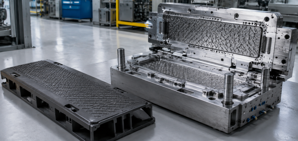
Plastic Cable Trench Cover Injection Mold
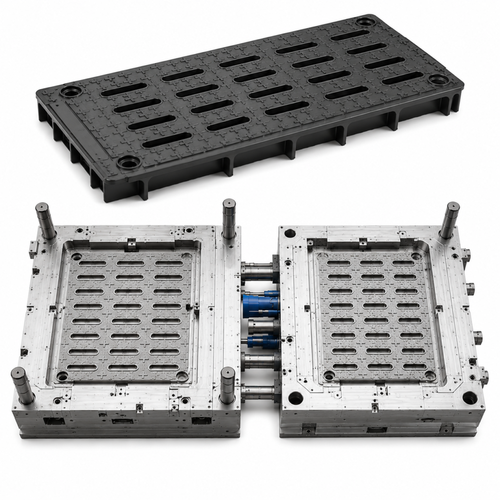
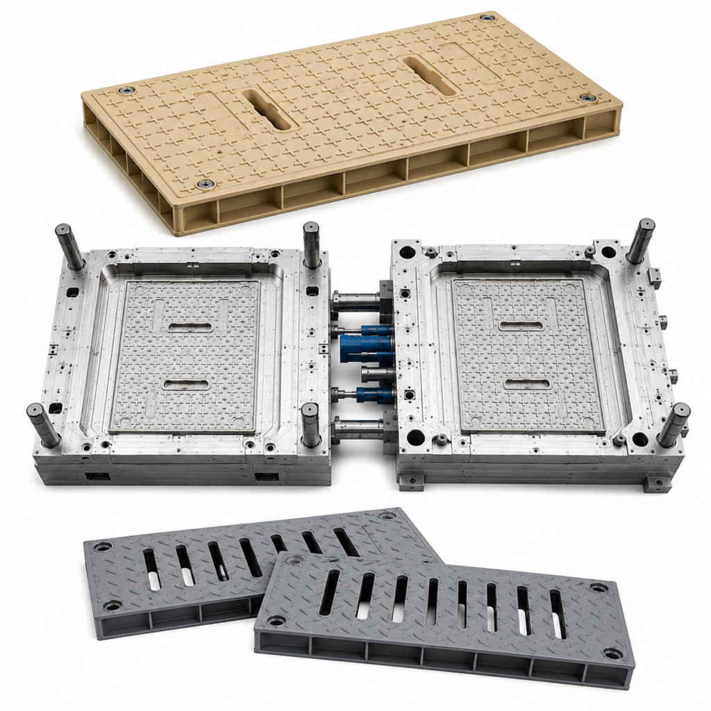
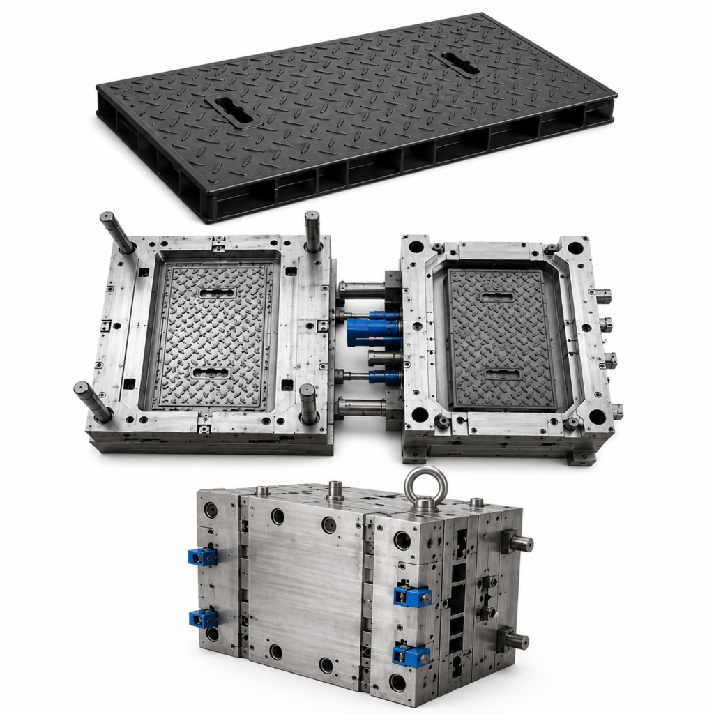
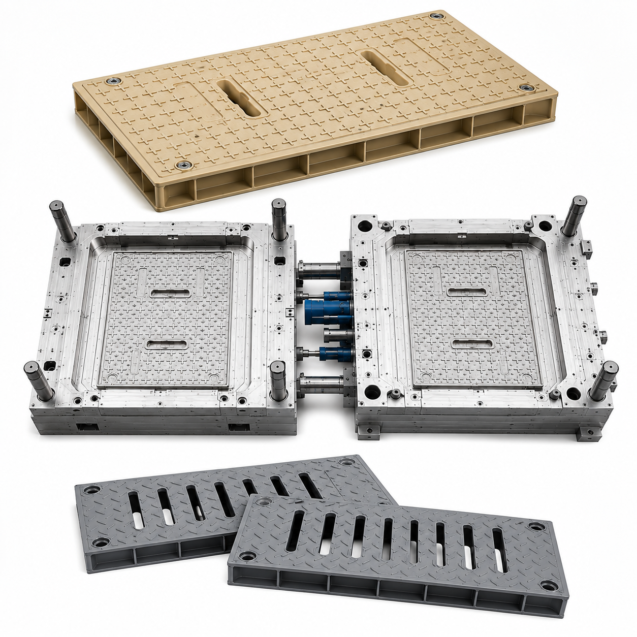
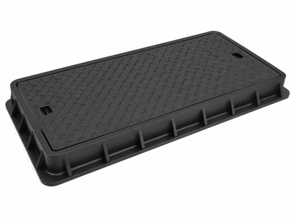
A Cable Trench Cover Injection Mold is used to manufacture plastic covers designed for cable trenches, electrical cable channels, underground wiring systems, utility infrastructure, industrial facilities, transportation projects, and outdoor electrical installations.
Compared with ordinary plastic covers, cable trench covers are often larger, thicker, and structurally more demanding. They may contain deep reinforcement ribs, anti-slip patterns, locating features, lifting holes, interlocking edges, mounting structures, or load-distribution zones.
These features create several challenges during injection mold design.
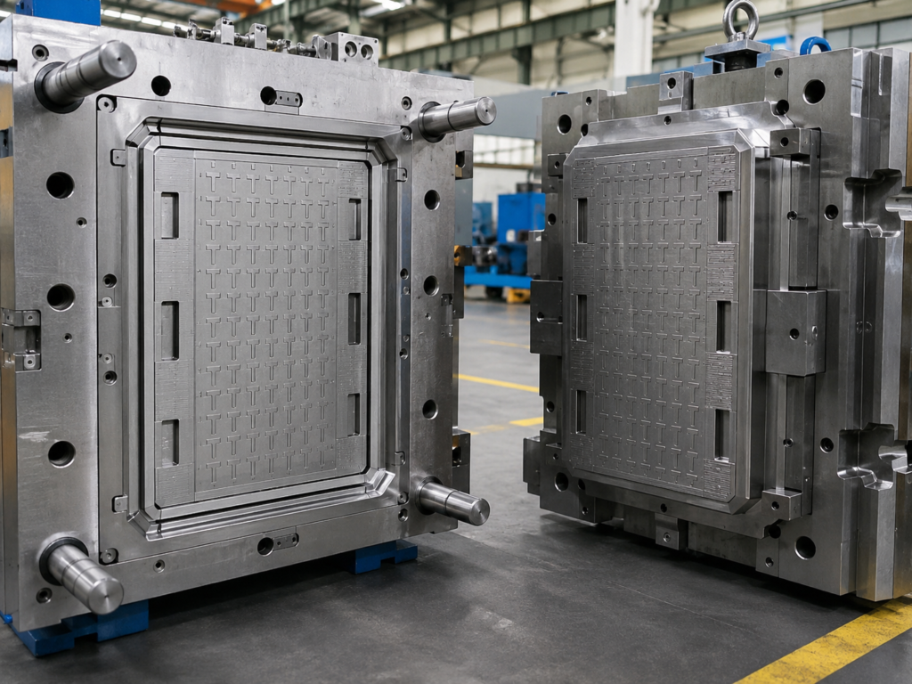
The mold must achieve balanced filling across a relatively large surface area while controlling shrinkage, warpage, sink marks, and dimensional variation. At the same time, the mold must provide sufficient mechanical strength to withstand repeated injection pressure during long-term mass production.
For injection mold buyers, the objective is not simply to manufacture an acceptable first sample. A professional Cable Trench Cover mold must deliver stable cycle performance, consistent dimensions, long mold life, reliable ejection, and reduced maintenance cost.
Cable Trench Cover Mold Specifications
The final tooling configuration should be determined according to product dimensions, resin, weight, annual volume, loading requirements, surface texture, injection molding machine size, and target mold life.
| Item | Typical Specification |
|---|---|
| Product | Cable Trench Cover |
| Mold Type | Plastic Injection Mold |
| Product Structure | Flat / Ribbed / Reinforced Cover |
| Mold Steel | P20 / 718H / H13 / S136 |
| Mold Base | LKM / HASCO / DME / Customized |
| Cavity | 1 Cavity / Customized |
| Runner System | Cold Runner / Hot Runner |
| Gate Type | Edge Gate / Fan Gate / Multiple Gates |
| Mold Life | 300,000–1,000,000+ Shots |
| Surface | Anti-Slip / Texture / Matte / Customized |
| Mold Trial | T0 / T1 / T2 / T3 |
| Application | Electrical / Utility / Infrastructure |
| Inspection | Dimensional & Functional Inspection |
The exact mold specification is confirmed after DFM review and analysis of the customer’s 3D drawing and production requirements.
Structural Mold Design for Heavy-Duty Cable Trench Covers
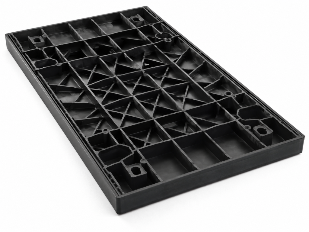
Cable trench covers frequently rely on reinforcement ribs to improve rigidity without excessively increasing product weight.
These rib structures are critical during mold design.
If ribs are too thick, sink marks may appear on the opposite cosmetic surface. If ribs are too thin or too deep, incomplete filling or difficult ejection may occur. Poorly designed intersections can also create localized shrinkage and internal stress.
During DFM analysis, the following areas should be carefully reviewed:
- Main wall thickness
- Rib thickness and depth
- Rib spacing
- Rib-to-wall ratio
- Draft angles
- Corner radii
- Bosses and locating structures
- Load-bearing areas
- Anti-slip textures
- Ejection direction
A balanced structural design improves both the molded component performance and mold manufacturability.
For complex rib areas, replaceable mold inserts can be used to simplify machining and future maintenance.
Mold Steel Selection and Mold Life
Mold steel has a direct influence on dimensional stability, wear resistance, maintenance frequency, and service life.
For standard production volumes, P20 or 718H can provide a practical combination of machinability, strength, and tooling cost.
For higher-volume production, demanding plastics, or applications requiring increased wear resistance, H13 or S136 may be considered for critical cavity, core, and insert areas.
| Mold Component | Material Option | Main Benefit |
| Cavity | 718H / H13 / S136 | Accuracy and durability |
| Core | 718H / H13 / S136 | Strength and wear resistance |
| Rib Inserts | H13 / S136 | Precision and replaceability |
| Mold Base | P20 / Standard Steel | Structural support |
| Guide Components | Hardened Steel | Reliable mold movement |
| Ejector System | Hardened Steel | Long-term wear resistance |
Premium steel does not necessarily need to be used throughout the entire mold.
A practical mold design applies high-performance materials primarily to critical wear zones, shut-off areas, inserts, and moving components.
This approach can improve mold life while maintaining reasonable tooling cost.
Gate and Runner Design
Gate design is particularly important for large Cable Trench Covers.
The molten plastic must travel over a relatively long flow distance while filling ribs, corners, edge structures, and other features before the material freezes.
A poorly positioned gate can create:
- Short shots
- Flow marks
- Weld lines
- Uneven packing pressure
- Excessive internal stress
- Verzug
- Sink marks
- Dimensional variation
For large covers, multiple gates or fan gates may be used to improve filling balance.
Hot runner systems can also be considered for high-volume production or large parts requiring reduced runner waste.
For demanding projects, mold flow analysis can be performed before mold manufacturing to evaluate:
- Filling balance
- Injection pressure
- Weld line locations
- Air traps
- Packing distribution
- Shrinkage
- Potential warpage
This allows the mold design to be optimized before steel cutting.
Cooling System and Warpage Control
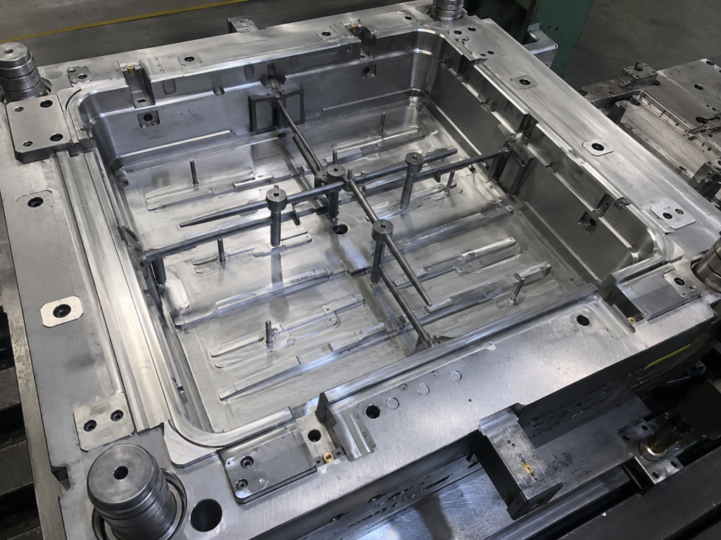
Cooling is one of the most important factors in Cable Trench Cover molding.
Large flat plastic parts are particularly sensitive to uneven mold temperature.
If one side cools faster than another, differential shrinkage can cause the cover to twist, bow, or become dimensionally unstable.
The cooling system should therefore provide uniform temperature control across:
- Central flat areas
- Reinforcement ribs
- Thick edge sections
- Mounting areas
- Corners
- Gate regions
Cooling channels should be positioned as close as safely possible to critical molding surfaces while maintaining sufficient mold steel strength.
Where conventional channels cannot provide sufficient cooling, additional cooling inserts or localized cooling solutions can be considered.
An optimized cooling design helps reduce:
- Cycle time
- Verzug
- Uneven shrinkage
- Residual internal stress
- Dimensional variation
It also improves long-term process stability.
Venting Design
A large reinforced Cable Trench Cover contains many long flow paths and enclosed rib intersections.
Air can easily become trapped as molten plastic fills these areas.
Poor venting may cause:
- Burn marks
- Short shots
- Incomplete ribs
- Surface defects
- Unstable filling
- Excessive injection pressure
Venting should be designed near last-to-fill areas, rib ends, corners, and other air-trapping locations.
Vent depth must be matched to the selected resin.
If vents are too shallow, air cannot escape effectively. If they are too deep, flash may occur.
Accurate machining and fitting are therefore essential.
Ejection System for Large Plastic Covers
Large flat molded parts can generate significant holding force during demolding.
For this reason, a Cable Trench Cover mold requires a carefully balanced ejection system.
Ejector pins should be distributed across structurally strong areas rather than concentrated in a few locations.
Depending on product geometry, the mold may use:
- Ejector pins
- Ejector sleeves
- Stripper structures
- Large-area ejector plates
- Combined ejection systems
The objective is to remove the molded part without causing deformation, whitening, cracking, or excessive ejector marks.
Adequate draft angles are also important, especially on deep reinforcement ribs.
During DFM analysis, difficult demolding areas should be identified before mold manufacturing.
Precision Mold Machining
A long-life injection mold depends on more than mold steel.
Machining precision determines how accurately the mold closes, fills, ejects, and repeats over hundreds of thousands of cycles.
Typical manufacturing processes include:
CNC Rough Machining → Heat Treatment → Precision CNC → EDM → Wire EDM → Grinding → Drilling → Mold Fitting → Assembly → Polishing or Texturing → Mold Trial
Large mold components require particular attention to machining deformation.
Machining sequences should therefore be planned to maintain flatness and dimensional stability.
Critical areas such as rib-forming inserts, shut-off surfaces, locating structures, and product edges should be checked during the manufacturing process.
Intermediate inspection helps prevent accumulated machining errors.
Mold Trial and Quality Inspection
Before mold shipment, multiple mold trials are normally performed to verify tooling performance.
During T0, T1, and subsequent trials, engineers evaluate:
- Filling condition
- Packing
- Cooling
- Ejection
- Surface quality
- Dimensions
- Verzug
- Sink marks
- Flash
- Cycle time
- Production repeatability
Typical inspection requirements include:
| Inspection Item | Purpose |
| Overall Length & Width | Confirm product dimensions |
| Thickness | Verify structural consistency |
| Flatness | Control warpage |
| Rib Dimensions | Confirm structural strength |
| Surface Texture | Verify anti-slip appearance |
| Edge Fit | Ensure installation accuracy |
| Ejection Marks | Confirm acceptable appearance |
| Mold Operation | Verify tooling reliability |
| Cycle Stability | Confirm mass-production performance |
For projects with stricter requirements, dimensional reports and mold trial records can be supplied together with sample parts.
Custom Cable Trench Cover Mold Development
Every Cable Trench Cover project has different requirements.
Product size, load capacity, rib geometry, surface texture, material, annual production volume, installation method, mold life, and injection molding machine capacity all influence the final tooling design.
A typical mold development process includes:
Product Drawing Review → DFM Analysis → Mold Flow Analysis if Required → Mold Design → Steel Preparation → CNC Machining → EDM → Mold Assembly → T0 Trial → Optimization → Final Trial → Inspection → Delivery
Common 3D file formats such as STEP, STP, X_T, IGES, and Parasolid can be reviewed before quotation.
For professional injection mold buyers, a high-quality Cable Trench Cover Injection Mold should provide more than acceptable first-off samples.
The mold should maintain reliable operation, consistent dimensions, controlled warpage, effective cooling, stable ejection, and long service life throughout mass production.
By combining proper structural analysis, high-precision machining, suitable mold steel, balanced gating, optimized cooling, effective venting, and systematic quality inspection, the mold can deliver stable production performance while reducing long-term tooling and maintenance costs.
