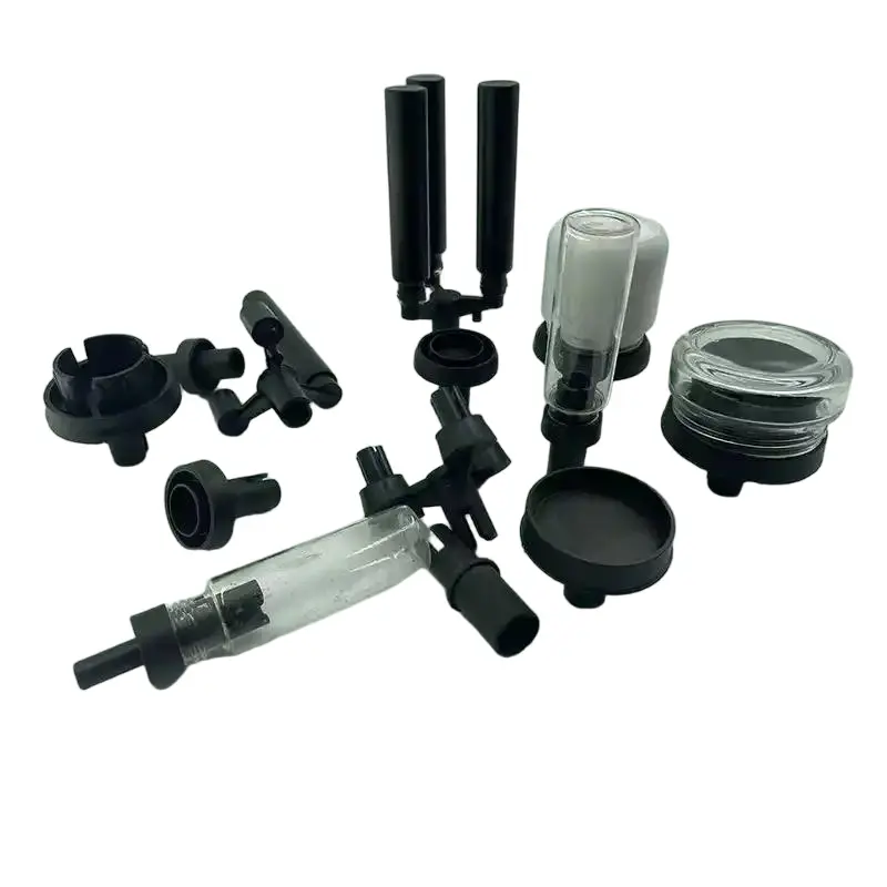
PA6/PA66+GF injection molding
- Home
- / Material /
- PA6/PA66+GF injection molding
Glass-Fiber Reinforced Nylon (GF-PA) Injection Moulding: The High-Performance Composite Solution
1. Introduction: Reinforcing Excellence
The incorporation of glass fibers into polyamide matrices represents one of the most significant advancements in engineering plastics technology. Glass-fiber reinforced nylons (GF-PA) combine the inherent benefits of polyamide—excellent mechanical properties, chemical resistance, and thermal stability—with the enhanced stiffness, dimensional stability, and heat resistance provided by fiber reinforcement. This synergistic combination creates materials capable of replacing metals in demanding applications while offering weight reduction, design freedom, and corrosion resistance.
From automotive underhood components to industrial machinery and electrical enclosures, GF-PA has become the material of choice where strength, stiffness, and dimensional precision are paramount. This comprehensive guide explores the specialized world of glass-fiber reinforced nylon injection moulding, addressing the unique challenges and opportunities presented by these advanced composite materials.
2. Material Science: The Reinforcement Mechanism
Reinforcement Fundamentals:
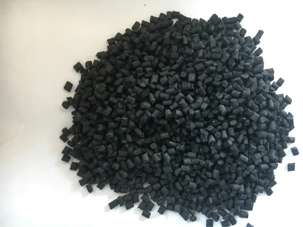
Glass-fiber reinforced nylons typically contain 10% to 50% glass fiber by weight, with 30% and 50% being the most common commercial grades. The reinforcement mechanism operates through several key principles:
Load Transfer Mechanism:
Fiber-Matrix Adhesion: Silane coupling agents chemically bond fibers to the nylon matrix
Stress Distribution: Fibers carry load more efficiently than the polymer matrix
Crack Propagation Inhibition: Fibers impede and deflect crack growth
Fiber Characteristics:
Type: E-glass most common; S-glass for higher performance
Length: Typically 0.2-0.4mm after compounding (original 3-6mm)
Diameter: 10-20 microns
Aspect Ratio: Critical for reinforcement efficiency (optimal: 20:1 to 40:1)
Property Enhancement Compared to Unreinforced PA:
| Property | Improvement vs. Unfilled PA | Typical Values (30% GF-PA6) |
|---|---|---|
| Tensile Strength | 2-3x increase | 160-200 MPa |
| Flexural Modulus | 3-5x increase | 8-10 GPa |
| Heat Deflection Temp | 100-150°C increase | 210-220°C @ 1.82 MPa |
| Creep Resistance | 10-100x improvement | Minimal deformation under load |
| Dimensional Stability | Significant improvement | 0.2-0.4% moisture expansion |
Fiber Orientation Effects:
Flow Direction: Fibers align with melt flow, creating anisotropic properties
Property Differential: 2-3x higher strength in flow direction vs. transverse
Design Consideration: Part design must account for anisotropic behavior
3. Material Preparation and Handling
Enhanced Drying Requirements:
Glass-filled nylons present more demanding drying requirements due to increased surface area and potential moisture entrapment:
Drying Specifications:
Temperature: 100-110°C for GF-PA6/66 (higher than unfilled grades)
Time: 6-8 hours minimum (extended for higher fiber content)
Target Moisture: <0.05% (500 ppm) for optimal processing
Dew Point: -40°C or lower mandatory
Consequences of Insufficient Drying: Severe splay, mechanical property loss, poor surface finish
Material Handling Challenges:
Abrasiveness: Glass fibers accelerate screw and barrel wear
Segregation: Fibers can separate from pellets during handling
Contamination: Special care needed to prevent contamination of unfilled materials
Static Electricity: More prone to static buildup
Regrind Management:
Maximum Regrind: 15-20% recommended (lower than unfilled PA)
Property Degradation: Fiber length reduction with each processing cycle
Separate Processing: Dedicate equipment for GF grades when possible
Testing Protocol: Regular mechanical testing to monitor property retention
4. Machine Configuration for GF-PA Processing
Specialized Equipment Requirements:
Barrel and Screw Modifications:
Screw Design:
Compression ratio: 2.0:1 to 2.5:1 (lower than unfilled PA)
L/D ratio: 18:1 to 20:1
Wear-resistant coatings: Tungsten carbide, bimetallic linings
Shallow flight depths: To minimize fiber breakage
Check Valve: Sliding ring type with hardened surfaces
Nozzle: Open nozzle with wear-resistant tip
Wear Protection:
Bimetallic Barrels: Hardened inner surfaces (Rc 58+)
Hardened Screws: Surface hardness Rc 60-65
Special Liners: For extreme abrasion resistance
Regular Inspection: Monitor screw and barrel wear
Clamping System:
Higher Tonnage: 4-7 tons per square inch (increased for higher viscosity)
Platen Parallelism: Critical for consistent fiber orientation
Ejection Force: Increased due to higher stiffness and shrinkage
5. Processing Parameters and Optimization
Temperature Settings for GF-PA:
| Parameter | 15% GF-PA66 | 30% GF-PA66 | 50% GF-PA66 |
|---|---|---|---|
| Rear Zone | 270-290°C | 280-300°C | 290-310°C |
| Middle Zone | 285-300°C | 295-310°C | 305-320°C |
| Front Zone | 295-310°C | 305-320°C | 315-330°C |
| Nozzle | 295-310°C | 305-320°C | 315-330°C |
| Melt Temp | 285-305°C | 295-315°C | 305-325°C |
| Mould Temp | 80-100°C | 90-110°C | 100-120°C |
Injection Phase Strategy:
Injection Speed:
Moderate to fast (optimize for fiber orientation)
Too slow: Poor fiber distribution
Too fast: Excessive fiber breakage and jetting
Injection Pressure: 1000-1600 bar (higher than unfilled grades)
Back Pressure: 5-15 bar (minimize fiber breakage)
Holding/Packing Phase:
Pressure: 50-70% of injection pressure
Time: Critical for dimensional stability
Function: Compensates for reduced shrinkage
Cooling Considerations:
Extended Cooling: GF-PA requires longer cooling than unfilled grades
Mould Temperature: Higher temperatures improve surface finish
Ejection Temperature: 100-120°C range
Fiber Length Preservation Strategy:
Moderate Screw Speed: 50-100 RPM optimal
Minimize Back Pressure: Only enough for melt homogeneity
Optimize Temperature: Avoid excessive heating zones
Proper Gating: Avoid restrictive gates that break fibers
6. Tooling Design for Glass-Filled Nylon
Enhanced Tooling Requirements:
Mould Material and Hardness:
Cavity/Core: Premium hardened steels (H13, S7, 420SS)
Hardness: 48-55 HRC minimum
Surface Treatments: Nitriding, chrome plating, or PVD coatings
Regular Maintenance: More frequent polishing and inspection
Runner and Gate Design:
Runner Size: Larger than unfilled grades (8-12mm diameter)
Full Round Runners: Essential for fiber preservation
Gate Design:
Size: 30-50% larger than for unfilled materials
Type: Tab gates preferred to reduce jetting
Location: Strategic to control fiber orientation
Hot Runners: Externally heated with temperature control ±3°C
Wear-Resistant Features:
Hardened Ejector Pins: Reduced galling and wear
Guide Bushings: Wear-resistant materials
Corrosion Protection: Essential for moisture resistance
Easy Maintenance: Design for frequent cleaning
Venting System:
Additional Vents: More vents than unfilled materials
Vent Depth: 0.020-0.035mm (slightly deeper)
Strategic Placement: At weld lines and end-of-fill areas
7. Part Design Considerations for GF-PA
Key Design Modifications:
Wall Thickness Optimization:
Uniformity: More critical than with unfilled PA (max 15% variation)
Minimum Thickness: 1.0-1.5mm (thicker than unfilled PA)
Thick Sections: Avoid when possible; core out if necessary
Radii and Corner Design:
Generous Radii: Minimum 1.0mm internal radius
Avoid Sharp Corners: Stress concentration exacerbated by fibers
Transition Design: Gradual changes in cross-section
Rib and Boss Design:
Rib Thickness: 40-50% of adjacent wall (thinner than unfilled PA)
Rib Height: Limited to 2.5x wall thickness
Boss Design: Must be well-supported with ribs
Draft Angles: Increased to 2-3° per side
Fiber Orientation Management:
Gate Location: Determines primary fiber orientation
Flow Path Design: Consider anisotropic properties in load-bearing areas
Weld Line Positioning: Place in low-stress areas
Shrinkage Considerations:
Differential Shrinkage: Flow direction: 0.2-0.4%; Transverse: 0.8-1.2%
Mould Design Compensation: Account for anisotropic shrinkage
Post-Mould Changes: Minimal compared to unfilled PA
8. Anisotropy Management and Warpage Control
Understanding Anisotropic Behavior:
GF-PA exhibits significantly different properties in flow direction versus transverse direction:
Property Anisotropy:
Tensile Strength: 2-3x higher in flow direction
Modulus: 2-2.5x higher in flow direction
Thermal Expansion: 3-4x higher in transverse direction
Shrinkage: 2-3x higher in transverse direction
Warpage Control Strategies:
Design-Level Solutions:
Symmetrical Rib Patterns: Balance fiber orientation
Uniform Wall Thickness: Minimize differential cooling
Strategic Gating: Control flow patterns and fiber alignment
Corner Reinforcement: Additional material at high-stress corners
Process-Level Solutions:
Optimized Mould Temperature: Higher temps reduce orientation
Balanced Filling: Multi-point gating for complex parts
Holding Pressure Optimization: Reduces differential shrinkage
Post-Mould Conditioning: Controlled cooling fixtures
Tooling Solutions:
Conformal Cooling: Uniform temperature distribution
Mould Surface Textures: Can help mask warpage effects
Adjustable Inserts: For fine-tuning dimensions
9. Surface Finish and Appearance Challenges
Common Surface Issues:
Fiber Read-Through (Fiber Bloom):
Appearance: Fibers visible on surface
Causes:
Improper processing conditions
Inadequate mould temperature
Excessive shear
Solutions:
Increase mould temperature (100-120°C)
Optimize injection speed
Use surface finish additives
Weld Line Weakness and Visibility:
Challenge: More pronounced than with unfilled PA
Strength Reduction: Up to 50-70% at weld lines
Improvement Strategies:
Increased melt and mould temperatures
Higher injection speed at weld areas
Strategic venting at weld locations
Surface Finish Options:
High-Gloss Finishes: Challenging but possible with optimal processing
Textured Surfaces: Effective at hiding fiber read-through
Painted Surfaces: Require proper surface preparation
Plated Surfaces: Special grades available for plating
Cosmetic Enhancement Techniques:
Mould Surface Treatments: Polished surfaces reduce fiber visibility
Processing Adjustments: Slower fill speeds for better surface
Additives: Surface modifiers and special colorants
Post-Mould Operations: Sanding, painting, coating
10. Secondary Operations and Assembly
Machining Considerations:
Tool Wear: Accelerated due to abrasive fibers
Tool Selection: Carbide or diamond-coated tools recommended
Cutting Parameters: Higher speeds, lower feeds
Cooling: Essential to prevent melting and tool damage
Joining Methods:
Mechanical Fastening:
Self-Tapping Screws: Successful with proper boss design
Inserts: Ultrasonic, thermal, or molded-in
Design Considerations: Account for higher stiffness and creep resistance
Welding and Bonding:
Ultrasonic Welding: Challenging but possible with energy directors
Vibration Welding: Most reliable method for GF-PA
Adhesive Bonding: Surface preparation critical (abrasion, primers)
Solvent Bonding: Not generally recommended
Post-Mould Treatments:
Annealing: Reduces molded-in stresses
Humidity Conditioning: Less critical than unfilled PA
Surface Coating: For improved appearance or functionality
11. Quality Control and Testing
Specialized Testing Requirements:
Fiber Characterization:
Fiber Length Distribution: Ashing method or image analysis
Fiber Orientation: Micro-CT scanning or microscopy
Fiber-Matrix Adhesion: Single fiber pull-out tests
Mechanical Testing Considerations:
Anisotropic Testing: Test specimens in multiple orientations
Notch Sensitivity: GF-PA is more notch-sensitive than unfilled PA
Fatigue Testing: Essential for dynamic applications
Non-Destructive Testing:
Ultrasonic Inspection: For internal defects
X-ray Imaging: For fiber orientation mapping
Thermal Imaging: For stress pattern analysis
Process Control Parameters:
Consistent Cushion: Critical for dimensional stability
Melt Temperature Monitoring: More critical than unfilled grades
Regular Screw Inspection: For wear monitoring
12. Advanced Applications and Case Studies
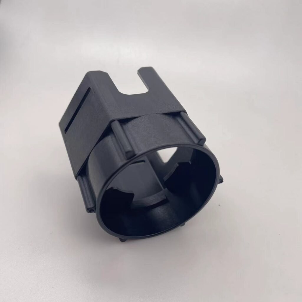
Automotive Structural Components:
Intake Manifolds: 30-35% GF-PA6 or PA66
Engine Covers: 30% GF-PA for heat resistance
Structural Brackets: Replacing metal with 50% GF-PA
Benefits: Weight reduction up to 50% vs. aluminum
Aerospace and Defense:
Drone Frames: High stiffness-to-weight ratio
Equipment Housings: EMI shielding capabilities
Structural Components: 50% GF-PA for maximum performance
Industrial Machinery:
Gears and Bearings: 30% GF-PA with internal lubrication
Pump Housings: Chemical resistance with structural integrity
Conveyor Components: Wear resistance and strength
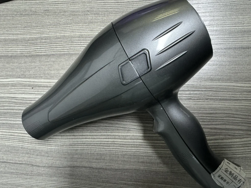
Electrical and Electronics:
Connector Housings: 15-30% GF-PA for dimensional stability
Circuit Breakers: Arc resistance and thermal properties
Enclosures: Flame retardant GF-PA grades
Sports and Recreation:
Bicycle Components: 30% GF-PA for strength and weight savings
Professional Equipment: Durability and performance
13. Troubleshooting GF-PA Specific Issues
| Problem | Root Causes | Corrective Actions |
|---|---|---|
| Excessive Fiber Breakage | High screw speed, excessive back pressure, restrictive flow | Reduce RPM to 50-100, minimize back pressure, enlarge gates/runners |
| Poor Surface Finish | Low mould temperature, fast injection, improper drying | Increase mould temp to 100-120°C, moderate injection speed, verify drying |
| Weld Line Weakness | Low temperatures, poor venting, improper gate design | Increase melt/mould temps, add vents at weld lines, relocate gates |
| Short Shots | High viscosity, inadequate pressure, restricted flow | Increase temperatures 10-20°C, increase pressure, enlarge flow channels |
| Warpage | Anisotropic shrinkage, non-uniform cooling, improper gate location | Optimize gate placement, improve cooling uniformity, consider sequential gating |
| Splay Marks | Moisture contamination, overheating, excessive shear | Verify drying (<0.05%), reduce melt temperature, moderate injection speed |
| Dimensional Variation | Inconsistent processing, worn tooling, inadequate packing | Standardize process, maintain tooling, optimize holding phase |
Preventive Maintenance Schedule:
Daily: Check and clean vents
Weekly: Inspect screw and barrel for wear
Monthly: Verify temperature calibration
Quarterly: Complete machine maintenance
14. Future Trends and Innovations
Advanced Fiber Technologies:
Long Fiber Reinforcements: Pellets with fibers up to 10mm length
Continuous Fiber Reinforcement: In-mould placement technologies
Hybrid Reinforcements: Glass + carbon fiber combinations
Nanofiber Reinforcements: Enhanced properties at lower loadings
Process Innovations:
In-Mould Sensor Integration: Real-time monitoring of fiber orientation
Adaptive Process Control: Automatic adjustment for consistent properties
Multi-Material Moulding: Combining GF-PA with other materials
Additive Manufacturing: 3D printing with fiber-reinforced filaments
Sustainability Initiatives:
Recycled Glass Fibers: From post-industrial or post-consumer sources
Bio-based Nylon Matrices: Renewable PA11/PA1010 with glass fibers
Improved Recyclability: Designed for mechanical or chemical recycling
Lightweighting: Further weight reduction for energy savings
Smart Materials Development:
Self-Healing Composites: Microcapsule technology for damage repair
Conductive Composites: For EMI shielding and static dissipation
Thermally Conductive Grades: For heat management applications
15. Conclusion: Mastering High-Performance Composites
Glass-fiber reinforced nylon injection moulding represents the convergence of material science, precision engineering, and practical processing expertise. Success with these advanced composites requires:
Respect for Material Characteristics: Understanding fiber-matrix interactions
Specialized Equipment: Properly configured for abrasive materials
Precise Process Control: Consistency is paramount for quality
Design for Manufacturing: Accounting for anisotropic behavior
Continuous Learning: Staying current with material and process innovations
The future of GF-PA lies in continued performance enhancement, improved sustainability, and expanded applications in demanding environments. As industries increasingly seek lightweight, durable alternatives to metals, glass-fiber reinforced nylons will play an ever-more critical role in product design and manufacturing.
For manufacturers venturing into or expanding their GF-PA capabilities, the investment in proper equipment, training, and process development yields significant returns in product performance, customer satisfaction, and competitive advantage. The challenges are substantial, but the rewards—in terms of product capabilities and market opportunities—are equally significant.