PC injection molding
- Home
- / Material /
- PC injection molding
Polycarbonate (PC) Injection Moulding: Mastering the High-Performance Engineering Plastic
1. Introduction: The Transparent Engineering Titan
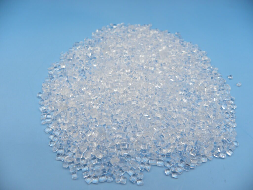
Polycarbonate (PC) stands as one of the most versatile and technically demanding engineering thermoplastics, renowned for its exceptional combination of optical clarity, impact resistance, and thermal stability. First commercially produced in the 1950s, PC has evolved from a specialty material to an industrial workhorse, finding critical applications where performance cannot be compromised. Unlike commodity plastics, PC injection moulding represents the pinnacle of precision processing, requiring meticulous attention to material science, process parameters, and tooling design to unlock its full potential.
This comprehensive guide explores the intricate world of PC injection moulding, from its molecular structure to advanced processing techniques. We will examine why PC is the material of choice for applications ranging from medical life-saving devices to aerospace components, and how mastering its processing challenges can yield products of extraordinary performance and reliability.
2. Material Science: Understanding the Polycarbonate Molecule
Chemical Structure and Synthesis
Polycarbonate derives its name from the carbonate groups (–O–(C=O)–O–) in its backbone, typically synthesized from bisphenol-A (BPA) and phosgene via interfacial polymerization or melt transesterification. This structure creates unique characteristics:
Key Structural Elements:
Aromatic Rings: Provide rigidity and high glass transition temperature (Tg ≈ 145-150°C)
Carbonate Linkages: Offer some chain flexibility and chemical functionality
Methyl Groups: Influence chain packing and free volume
Material Grades and Their Specializations:
| Grade Type | Key Characteristics | Applications |
|---|---|---|
| Optical Grade | 90%+ light transmission, low haze | Lenses, optical discs, display covers |
| Medical Grade | USP Class VI, ISO 10993 compliant | Surgical instruments, drug delivery devices |
| Flame Retardant | UL94 V-0/V-2 ratings, halogen-free options | Electrical enclosures, aviation interiors |
| Glass-Filled | 10-40% glass fiber reinforcement | Structural components, automotive parts |
| Impact Modified | Enhanced low-temperature toughness | Protective equipment, safety components |
| FDA Food Contact | Compliance with food safety regulations | Water bottles, food processing equipment |
Physical Properties Overview:
Density: 1.20-1.22 g/cm³
Refractive Index: 1.584 (excellent optical properties)
Tensile Strength: 55-75 MPa
Notched Izod Impact: 600-850 J/m (exceptionally high)
Heat Deflection Temperature: 130-140°C @ 1.82 MPa
Water Absorption: 0.15-0.35% (24h immersion)
3. Material Handling: The Critical Pre-Processing Phase
The Imperative of Proper Drying
PC is extremely hygroscopic, absorbing up to 0.35% moisture at equilibrium. Improper drying leads to irreversible molecular degradation:
Drying Specifications:
Target Moisture: <0.02% (200 ppm) for optical grades; <0.04% for general purpose
Drying Temperature: 120°C for standard grades; 135°C for high-heat grades
Drying Time: Minimum 4-6 hours; thick pellets may require 8+ hours
Dew Point: -30°C or lower (desiccant dryers recommended)
Hopper Management: Closed-loop drying hoppers with 1-2 hour residence time
Consequences of Insufficient Drying:
Hydrolytic Degradation: Water reacts with carbonate links, reducing molecular weight
Molecular Weight Drop: Directly correlates with impact strength loss
Visual Defects: Splay marks, silver streaks, bubbles
Mechanical Property Loss: Up to 80% reduction in impact strength possible
Regrind Management Strategy:
Maximum Regrind: 20-25% for critical applications
Thermal History Monitoring: Each heat cycle reduces molecular weight
Separate Drying: Regrind often requires longer drying times
Testing Protocol: Regular MFI testing to monitor degradation
4. Injection Moulding Machine Configuration for PC
Machine Selection Criteria:
Clamp Capacity: 3-6 tons per square inch of projected area
Injection Unit: Sized for 40-80% of machine shot capacity
Drive Type: Electric or hybrid preferred for precise control
Screw Design Requirements:
Type: General purpose or gradual compression screw
L/D Ratio: 20:1 to 24:1 (longer for better melt homogeneity)
Compression Ratio: 2.0:1 to 2.5:1
Check Valve: Sliding ring type with minimal dead space
Screw Tip: Mixing elements recommended for color dispersion
Barrel and Nozzle Specifications:
Barrel Zones: Minimum 4 zones with PID temperature control
Nozzle Type: Open nozzle standard; shut-off for drool prevention
Temperature Control: ±2°C accuracy required
Capacity: Screw diameter should provide adequate shear heating
5. Processing Parameters: Precision Control Requirements
Temperature Settings by Application:
| Application | Melt Temperature | Mould Temperature | Special Considerations |
|---|---|---|---|
| Optical Parts | 300-320°C | 80-110°C | Highest temperatures for clarity |
| Thin-Wall Parts | 310-330°C | 70-90°C | Fast injection needed |
| Structural Parts | 290-310°C | 60-80°C | Lower temps for dimensional stability |
| Medical Components | 300-315°C | 70-90°C | Strict temperature documentation |
Zone-by-Zone Temperature Profile:
Rear Zone: 260-280°C (gentle preheating)
Middle Zones: 280-310°C (gradual temperature rise)
Front Zone: 300-320°C (final melt homogenization)
Nozzle: 300-320°C (matched to front zone)
Injection Phase Parameters:
Injection Speed: Fast to very fast (prevents premature freezing)
Injection Pressure: 800-1500 bar (adjust based on flow length)
Boost/Pack Switch: 95-98% cavity fill (critical for pressure control)
Holding/Packing Phase Strategy:
Pressure: 50-70% of injection pressure
Time: Until gate freeze (typically 5-20 seconds)
Profile: Multiple-stage pressure decay often beneficial
Cooling and Cycle Optimization:
Cooling Time: 40-70% of total cycle (depends on wall thickness)
Ejection Temperature: Below 100°C (to prevent stress marks)
Cycle Time: Typically 40-120 seconds
6. Tooling Design Excellence for PC
Mould Material Selection:
Production Moulds: H13, S7, or stainless steel (420SS or 440C)
Surface Hardness: 48-52 HRC minimum
Cavity Polish: SPI A-1 or better for optical parts
Corrosion Protection: Chrome plating or nitriding recommended
Runner System Design:
Full Round Runners: 6-10mm diameter minimum
Hot Runners: Externally heated with precise temperature control
Gate Types:
Tab Gates: For reducing jetting
Diaphragm Gates: For cylindrical parts
Direct Hot Tips: For cosmetic parts
Cooling System Criticality:
Channel Design: Conformal cooling preferred for complex parts
Temperature Control: ±2°C across mould surface
Circuit Layout: Separate circuits for cores and cavities
Coolant Flow: Turbulent flow for maximum heat transfer
Venting Specifications:
Vent Depth: 0.015-0.025mm (shallower than many materials)
Vent Width: 6-12mm
Vent Placement: Every 25-50mm along parting line
Special Vents: At weld lines and end-of-fill areas
Ejection System Design:
Ejector Pins: Larger diameter pins for lower surface pressure
Stripper Plates: For thin-walled cylindrical parts
Air Ejection: For optical parts requiring mark-free surfaces
7. Part Design Guidelines for Polycarbonate
Wall Thickness Principles:
General Range: 1.5-4.0mm
Optimal Thickness: 2.5-3.0mm for best flow/strength balance
Uniformity: Critical (maximum 15% variation)
Thick Sections: Core out to prevent sink marks and reduce cycle time
Rib Design Strategy:
Rib Thickness: 40-50% of adjacent wall
Rib Height: Maximum 3 times wall thickness
Rib Spacing: Minimum 2.5 times wall thickness
Draft Angles: 1-2° per side
Corner and Transition Design:
Internal Radii: 0.5-1.0 times wall thickness
External Radii: Internal radius plus wall thickness
Tapered Transitions: For thickness changes >25%
Draft Angle Requirements:
Optical Surfaces: 0.5-1° per side minimum
Textured Surfaces: 3° per side plus 1° per 0.025mm texture depth
Deep Draw Parts: Additional 0.5-1° per 25mm depth
Living Hinge Design (PC-specific):
Thickness: 0.25-0.50mm
Width: 1.5-3.0mm
Radii: Generous radii at hinge ends
Orientation: Perpendicular to flow direction
8. Troubleshooting: Addressing PC-Specific Challenges
Critical Defects and Solutions
| Defect | Root Causes | Corrective Actions |
|---|---|---|
| Splay/Silver Streaks | Moisture contamination, overheated melt | Verify drying (<0.02%), reduce melt temp, check check valve |
| Bubbles/Voids | Moisture, excessive holding pressure, short packing | Improve drying, reduce holding pressure, increase pack time |
| Weld Lines | Low melt temp, slow injection, poor gate location | Increase temp 10-20°C, increase speed, relocate gates |
| Residual Stress | Rapid cooling, high packing pressure, improper ejection | Increase mould temp, reduce pack pressure, optimize ejection |
| Chemical Crazing | Stress + chemical exposure (IPA, cleaners) | Reduce stress through design/process, avoid chemical exposure |
| Yellowing | Thermal degradation, excessive regrind, UV exposure | Lower melt temp, reduce regrind %, add UV stabilizers |
| Jetting | Gate too small, injection too fast, cold mould | Enlarge gate, use tab gate, increase mould temperature |
| Sticking | Undercuts, insufficient draft, high mould temp | Add draft, polish core, lower mould temperature |
Material Degradation Monitoring:
Melt Flow Index: Regular testing (increase indicates degradation)
Color Measurement: Spectrophotometer for yellowing detection
Impact Testing: Periodic checks for property retention
FTIR Analysis: For chemical structure verification
9. Post-Processing and Secondary Operations
Stress Relief Annealing:
Necessity: Critical for parts with residual stress or chemical exposure
Temperature: 125-135°C (10-20°C below Tg)
Time: 1-4 hours depending on wall thickness
Cooling Rate: 1-2°C per minute to room temperature
Machining and Finishing:
Machinability: Good with sharp tools and proper cooling
Drilling/Tapping: Use positive rake angles and peck drilling
Polishing: Successive grits to restore optical clarity
Coatings: Hard coats for abrasion resistance (silicone-based)
Joining and Assembly:
Solvent Bonding:
Solvents: Methylene chloride, ethylene dichloride
Process: Capillary action with proper fixturing
Strength: 80-100% of base material
Ultrasonic Welding:
Energy directors required
Near-field welding (<6mm) preferred
Adhesive Bonding:
Epoxies, cyanoacrylates, or UV-cure adhesives
Surface treatment may be required
Decorative Processes:
Painting: Requires adhesion promoters
Metallization: Vacuum metallization for reflective surfaces
Printing: Pad printing, screen printing, or digital printing
Laser Marking: High contrast marks possible
10. Advanced Processing Techniques for PC
Multi-Material/Overmoulding:
PC/TPU Combinations: For soft-touch grips on rigid substrates
PC/PC Combinations: For two-shot color effects
Mould Requirements: Precise temperature control for each material
In-Mould Decoration (IMD):
Film Types: PC, PET, or multilayer films
Applications: Automotive interiors, appliance panels
Challenges: Film handling, adhesion, optical clarity maintenance
Microcellular Foam Moulding:
Benefits: Weight reduction (5-30%), reduced sink marks
Challenges: Surface quality, strength reduction
Applications: Thick structural parts, large panels
Injection-Compression Moulding:
Benefits: Lower stress, better optical properties
Process: Partial injection followed by mould compression
Applications: Large optical components, lenses
Clean Room Moulding:
Requirements: ISO Class 7 or better
Applications: Medical, optical, data storage
Considerations: Material handling, machine enclosures, personnel training
11. Quality Control and Material Testing
Process Control Parameters:
Melt Temperature: Infrared pyrometer verification
Mould Temperature: Surface probes at multiple locations
Cushion Consistency: ±0.5mm variation maximum
Cycle Time: Statistical process control charts
Material Characterization Tests:
Rheological:
Melt Flow Rate (ASTM D1238)
Capillary rheometry for viscosity curves
Mechanical:
Tensile (ASTM D638)
Impact (ASTM D256, D3763)
Flexural (ASTM D790)
Thermal:
DSC for Tg and crystallinity
TGA for thermal stability
HDT (ASTM D648)
Optical:
Haze and transmission (ASTM D1003)
Refractive index
Yellowness index (ASTM D1925)
Part Validation Testing:
Dimensional: CMM with temperature-controlled environment
Optical: Interferometry for surface quality
Stress Analysis: Polarized light or photoelastic methods
Environmental: Thermal cycling, humidity exposure, chemical resistance
12. Industry Applications and Case Studies
Automotive Industry:
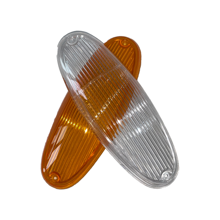
Headlamps: Complex optics requiring clarity and heat resistance
Glazing: Sunroofs, side windows (weight reduction vs. glass)
Components: Connectors, sensors, interior trim
Medical Technology:
Surgical Instruments: Autoclavable, transparent
Drug Delivery: Transparency for fluid monitoring
Equipment Housings: Impact resistance and cleanability
Electronics and Electrical:
Connectors: UL94 V-0 requirements
Enclosures: EMI shielding options
Displays: Touch screen covers, light guides
Aerospace and Defense:
Windows and Canopies: Impact resistance and optical quality
Components: Lightweight structural parts
Protective Gear: Visors, shields
Consumer Products:
Eyewear: Prescription lenses, safety glasses
Appliances: Transparent doors, components
Packaging: Medical, high-value product packaging
13. Sustainability and Future Directions
Recycling Challenges and Solutions:
Mechanical Recycling: Limited by thermal degradation
Chemical Recycling:
Hydrolysis: Back to BPA and carbonate sources
Glycolysis: For polyol production
Pyrolysis: For chemical feedstocks
Closed-Loop Systems: Developing for specific applications
Bio-based and Alternative Materials:
BPA-Free PC: Isosorbide-based polymers
Bio-PC: Partially bio-based monomers
Performance: Similar optical and mechanical properties
Energy Efficiency Initiatives:
All-Electric Machines: Precise control for energy savings
Heat Recovery: From cooling systems
Process Optimization: Reduced cycle times through simulation
Emerging Technologies:
Nano-composites: Enhanced properties at lower weight
Self-healing PC: Microcapsule technology
Smart PC: Integrated sensors or functional additives
14. Conclusion: The Clear Choice for Demanding Applications
Polycarbonate injection moulding represents a sophisticated intersection of material science and precision engineering. Its successful processing demands respect for the material’s characteristics—particularly its hygroscopic nature and sensitivity to thermal history—combined with meticulous attention to every aspect of the manufacturing process.
The future of PC lies in balancing its exceptional performance with growing sustainability demands. Advances in recycling technologies, bio-based alternatives, and processing efficiency will ensure PC remains relevant in an increasingly environmentally conscious market. For manufacturers, the key to success with PC is developing deep process knowledge, implementing rigorous quality control, and maintaining flexibility to adopt new technologies and methods.
As applications become more demanding—whether in thinner walls, higher optical clarity, or enhanced sustainability profiles—PC injection moulding professionals must continue to push the boundaries of what is possible with this remarkable engineering material.